How to Design an Industrial Dust Collection System for Factories
An industrial dust collection system should start from the process, not from the dust collector model. The collector, fan, ductwork, hood and control strategy must work together. If one part is selected without the others, the system may look complete on paper but fail to capture dust in production.
This PureAirTek guide explains a practical design sequence for factories, engineering contractors and distributors. It focuses on real workshop questions: where dust is generated, how air should move, how pressure loss is controlled and how the final system can be accepted after installation.
Industrial Dust Collection Design Sequence
- Map every dust source and classify the dust behavior.
- Decide whether each source needs enclosure, hood capture or direct machine connection.
- Calculate airflow by source and apply a simultaneity factor only when the production schedule supports it.
- Plan duct routes that keep transport velocity stable and reduce unnecessary elbows.
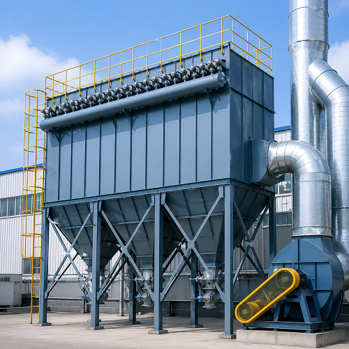
- Select baghouse, cartridge, cyclone or hybrid equipment based on dust load and maintenance needs.
- Calculate total static pressure and select a fan from the operating point on the fan curve.
- Define commissioning data, inspection access and filter maintenance responsibilities.
Source Capture Comes First
Many systems fail because the hood is too far from the dust source. A stronger fan cannot fully correct poor capture geometry. Grinding tables, cutting stations, CNC routers, bag dumping points and mixer openings each need a different capture method. The closer and more enclosed the capture point is, the lower the required airflow can be.
| Dust Source | Preferred Capture Method | Design Note |
| CNC woodworking machine | Direct port connection | Check port diameter, spindle enclosure and chip loading. |
| Manual grinding table | Downdraft or backdraft hood | Keep sparks and abrasive dust away from filters where needed. |
| Powder dumping | Partial enclosure with local extraction | Operator movement and bag handling must be considered. |
| Laser or plasma cutting | Table extraction zones | Airflow must match the active cutting area, not only total table size. |
Centralized or Decentralized
A centralized system is suitable when many stable sources operate in the same production area and a single duct route can be balanced. It can simplify maintenance and reduce the number of collectors. A decentralized layout is better when sources are far apart, production changes often, dust types should not mix, or one high-risk process needs separate safety control.
PureAirTek normally reviews the layout before recommending one direction. A factory may use both: a central baghouse for woodworking machines and a smaller cartridge collector for a welding or grinding cell.
Collector Selection Logic
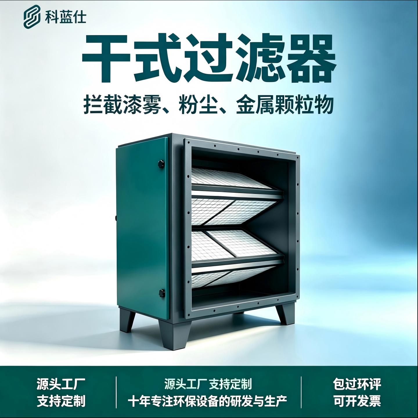
- Baghouse dust collectors suit high dust loading, larger airflow and continuous operation.
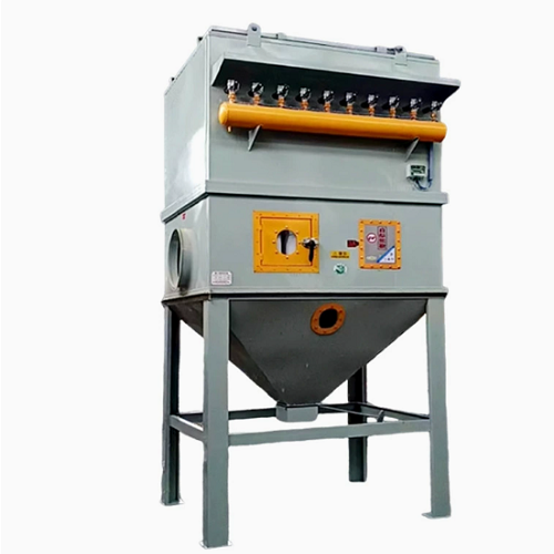
- Cartridge dust collectors suit fine dust, welding fumes and compact installation space.
- Cyclone collectors can reduce coarse dust before final filtration.
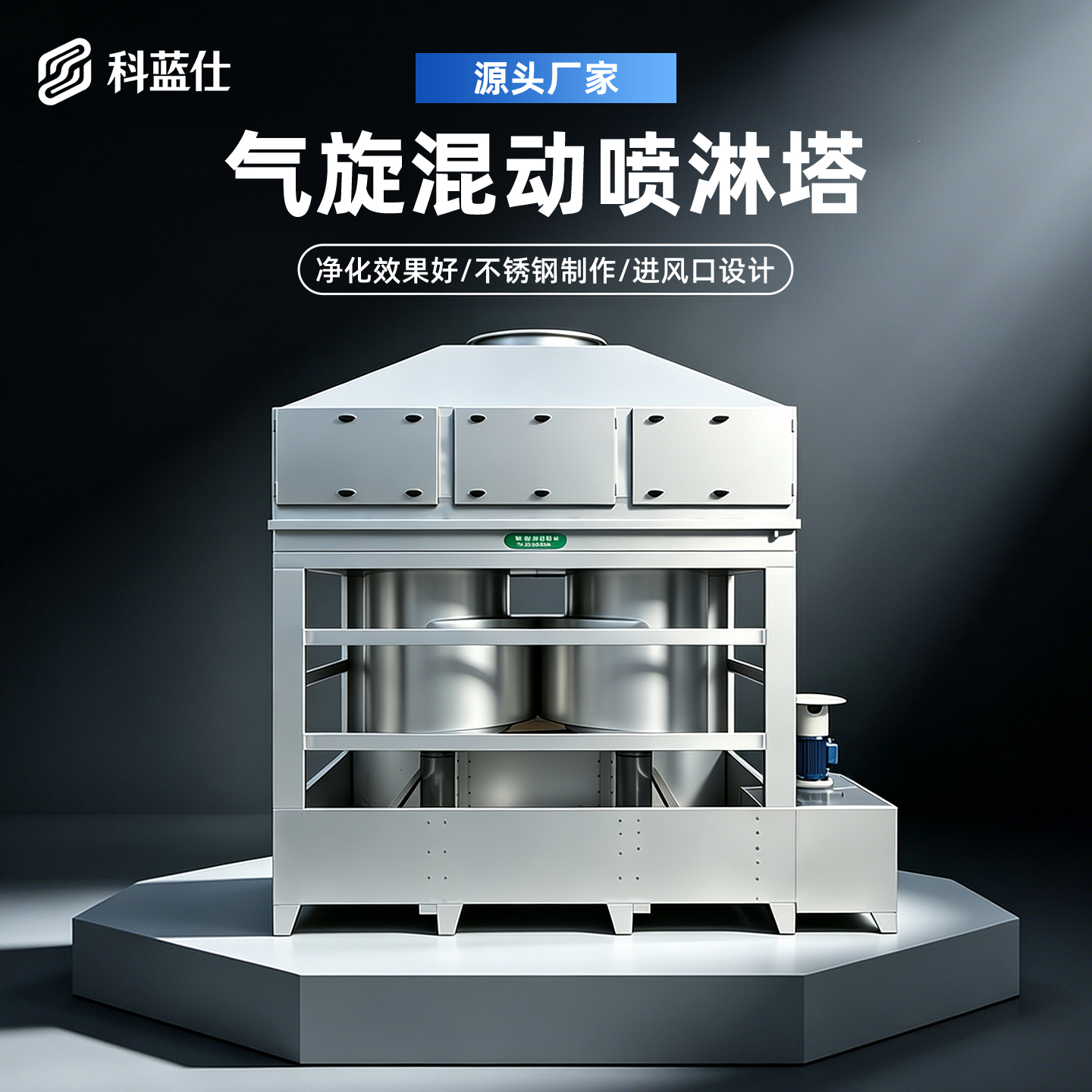
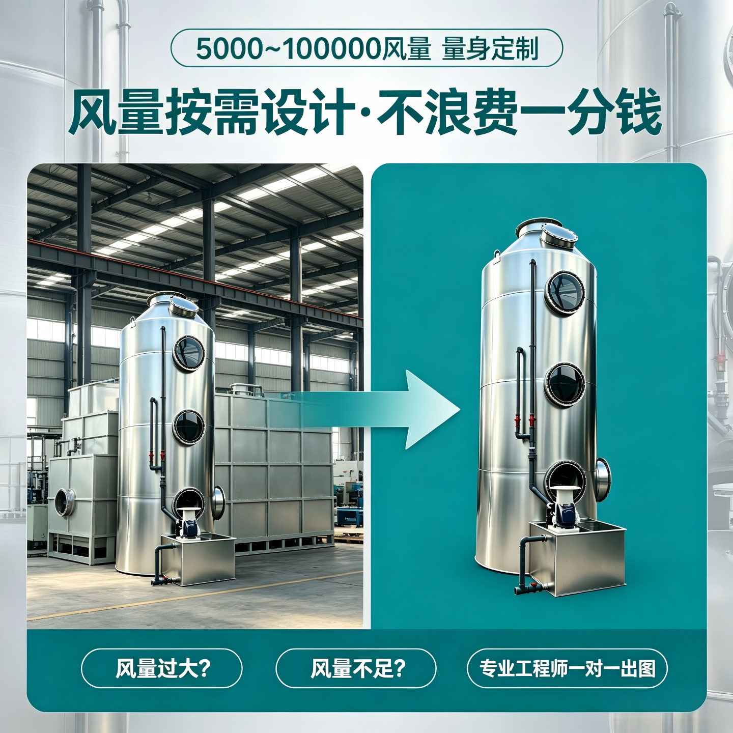
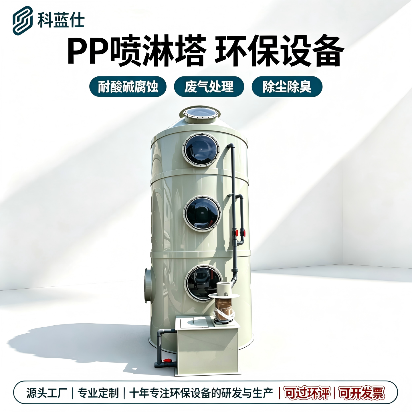
- Wet scrubbers may be reviewed when dust is sticky, hot, explosive or mixed with soluble gas.
Acceptance Data
A good design includes an acceptance plan. After installation, record branch airflow, collector differential pressure, pulse pressure, fan current, damper positions and visible capture results. These numbers become the baseline for later troubleshooting. Without baseline data, it is difficult to know whether a future issue comes from blocked filters, changed production or incorrect duct balancing.
Information to Send for Design Review
Send workshop layout, machine list, dust source photos, material type, operating hours, existing duct route if any, voltage, installation space and emission target. PureAirTek can use this information to recommend a practical system layout before quoting equipment.