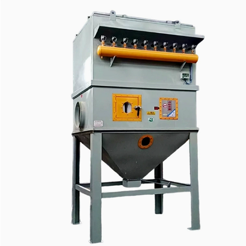
Industrial Exhaust Pretreatment Equipment Selection Guide
Pretreatment is the stage that makes the main control device work reliably. It should remove or stabilize the contaminant that would otherwise foul, ignite, corrode or overload the downstream collector, adsorber, concentrator or oxidizer. The correct pretreatment train is determined by the process exhaust, not by a generic equipment list.
Classify the exhaust before choosing equipment
| Dominant upstream problem | Typical pretreatment purpose |
|---|---|
| Coarse dust, chips or abrasive solids | Separate mass loading before fine filtration. |
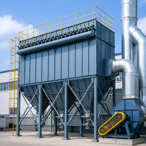
| Fine dry dust | Use suitable filtration and manage resistance/cleaning. |
| Paint mist, oil aerosol or sticky material | Capture droplets and protect carbon or catalyst surfaces. |
| Hot gas or thermal peaks | Cool or dilute only after checking condensation and safety effects. |
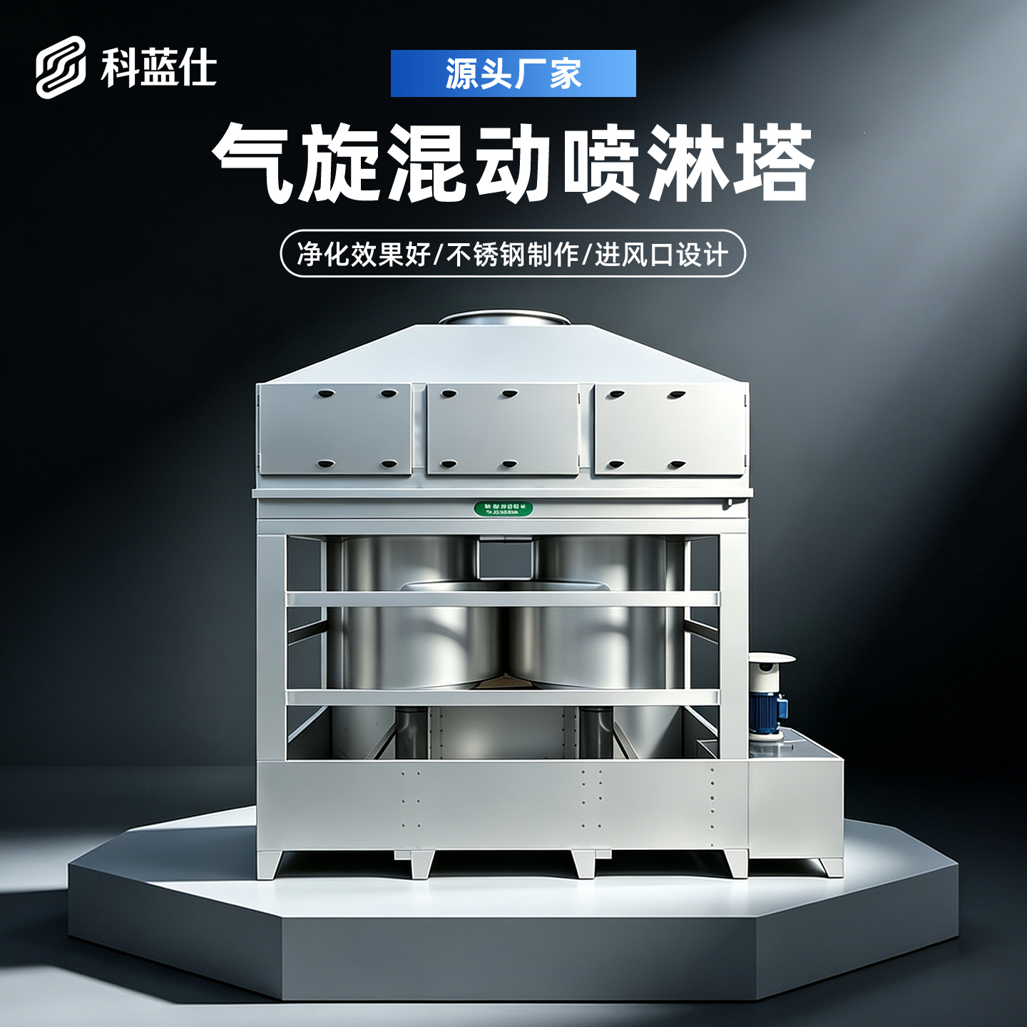
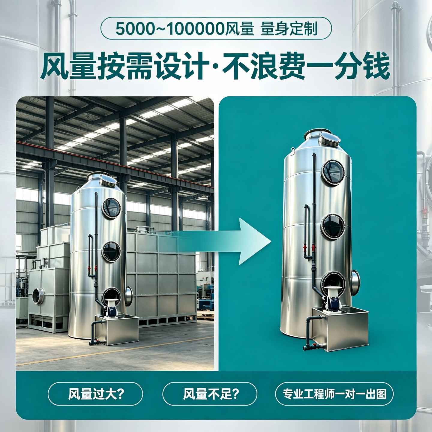
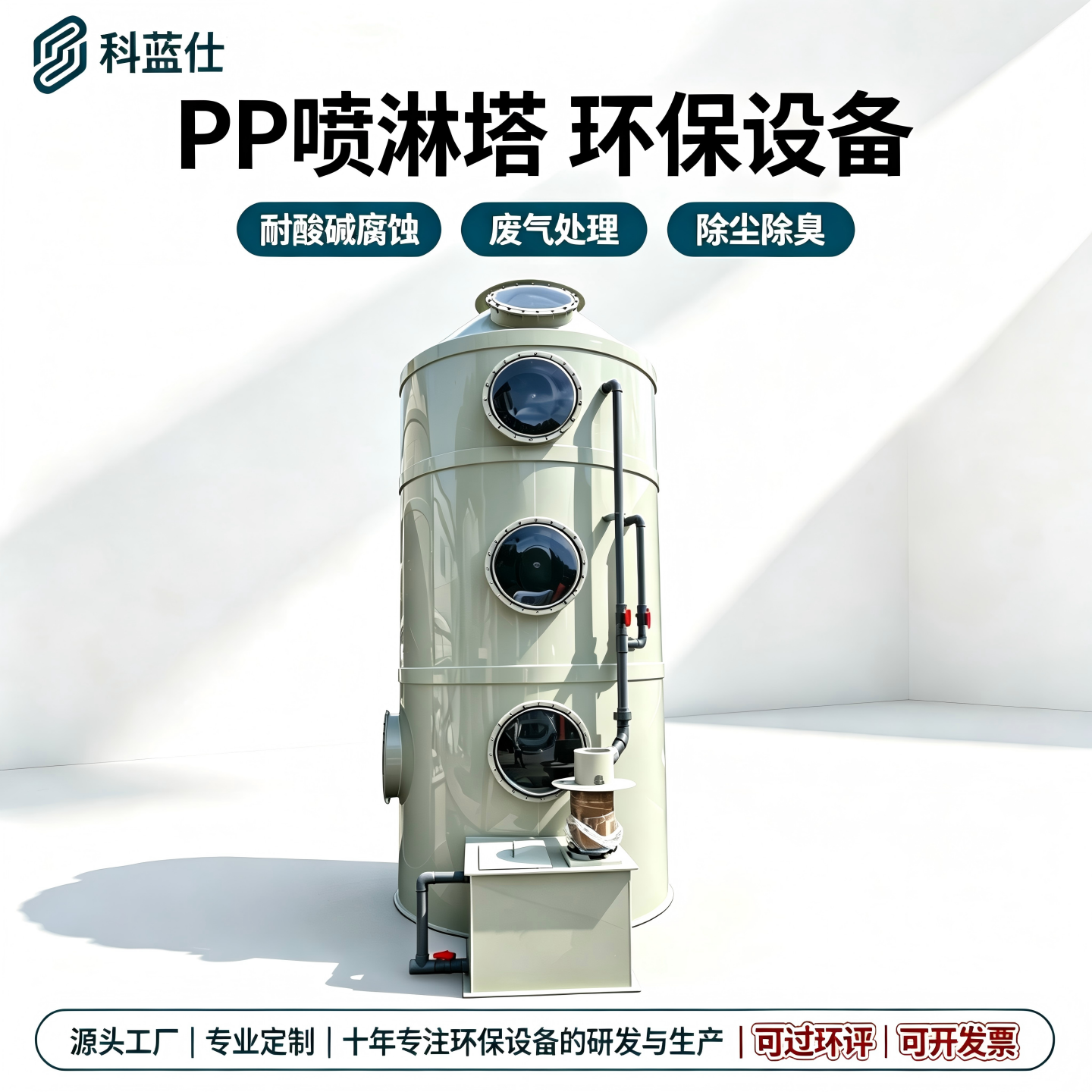
| Acid/alkaline soluble gases | Use wet reaction or absorption where chemistry supports it. |
| Sparks or combustible dust | Assess isolation, spark management and explosion risk as a system. |
Common process trains, with their limits
For paint exhaust, mist separation and dry filtration may precede carbon adsorption or a thermal process. For dusty process air, a primary separator or dust collector protects later stages. For chemically reactive gases, a scrubber can be appropriate, but it introduces liquid management. For high-concentration VOCs, the decision can involve dilution, concentration, recovery or oxidation based on the compound and operating profile.
Avoid four common selection mistakes
- Choosing a final-treatment device without measuring upstream dust, mist, temperature and humidity.
- Putting a filter upstream without enough area, access or differential-pressure monitoring.
- Using a wet stage without a plan for reagent control, sludge and blowdown.
- Assuming one train fits every shift, product formulation or seasonal condition.
Design around stable operation
A pretreatment package should show airflow range, pressure-drop budget, fan position, drain points, inspection doors, replacement method and interlocks. The aim is not maximum equipment count; it is a stable inlet condition for the next stage and a maintenance routine that operators can actually perform.
Information for a practical recommendation
Provide the process description, airflow, contaminants, temperature, moisture, visible particulate/mist, production hours, target outlet requirement, utilities and available footprint. A good supplier should turn this into a stated design basis and explain why every upstream stage is included.